Leave Your Message

How to Choose the Right Rod End Cylinder?

Choosing the right Rod End Cylinder begins with the job it must perform, not the catalog photograph. A cylinder that fits neatly between two brackets can still fail if its stroke, force, or mounting geometry is wrong. Hydraulic design engineer Daniel Mercer offers a useful rule: “Match the cylinder to the load path, not just the available space.” That principle matters when a rod-end bearing must follow a moving linkage without binding.

Start by defining the required push or pull force, operating pressure, stroke, and cycle rate. Then measure the pin diameter, center-to-center length, and available clearance at both ends of travel. A few millimeters can change the mounting angle. Check whether the load stays aligned with the rod; side loading can accelerate wear on bearings, seals, and the rod itself. Consider whether the cylinder needs single-acting or double-acting operation, and specify suitable materials and seals for dust, moisture, or temperature changes. Small details count.

The best choice is rarely the largest cylinder that fits. Oversizing can add weight, consume space, and create unnecessary stress elsewhere in the mechanism. Undersizing can mean slow movement, overheating, or premature wear. Real installations are imperfect: brackets flex, loads shift, and maintenance access gets overlooked. Leave room to inspect the rod end and replace seals. Before ordering, compare the manufacturer’s drawings with the actual assembly, and confirm dimensions with the supplier. A careful check now can prevent a costly mismatch later.
How to Choose the Right Rod End Cylinder?

Identify the Application and Operating Requirements

How to Choose the Right Rod End Cylinder?

Identify the Application and Operating Requirements

Start with the job the cylinder must perform. Note the load, required stroke, operating pressure, and movement speed. A cylinder moving a light gate needs different capacity from one positioning a loaded fixture. Record how often it cycles, too. Repeated starts and stops can change wear and heat conditions. A first estimate may miss those details; check the actual duty cycle before selecting a model.

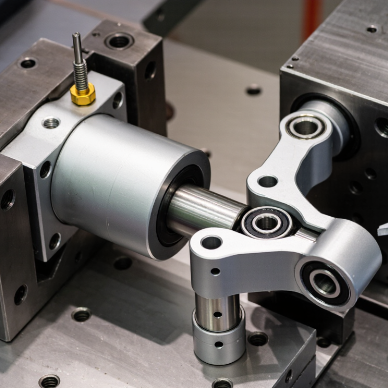
Look closely at the mounting points and surrounding space. Measure the available length with the cylinder fully retracted and extended. Check whether the rod end must accommodate angular movement, and confirm the permitted misalignment in the product specifications. Side loads deserve particular attention. A rod-end joint can allow movement, but it does not automatically protect the rod from bending. Consider dust, moisture, temperature, and nearby washdown when choosing seals and materials. Small details matter.

Tips: Write down the load, stroke, pressure, speed, cycle rate, and environment. Compare these values with rated limits, leaving a practical margin for changing conditions. If you are unsure about shock loads or alignment, ask a qualified supplier or engineer to review your measurements. Don’t guess.

Choose the Cylinder Type and Mounting Configuration

Choose the cylinder type around the motion and load, not just the available space. A double-acting cylinder controls extension and retraction; a single-acting model uses pressure in one direction and a spring or external force in the other. For pneumatic designs, ISO 15552 specifies cylinder dimensions and mounting interfaces across bore sizes from 32 to 320 mm. That range helps compare compatible layouts, but it does not determine the force you need. Check pressure, bore, stroke, speed, and duty cycle against the actual load.

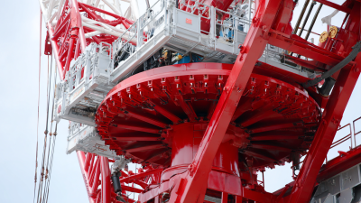
Mounting decides how the cylinder reacts to movement. A clevis or trunnion mount can pivot with an articulated linkage; a flange or foot mount suits more rigid installation. Alignment matters. Side load can accelerate seal and rod wear, even when the cylinder’s rated force looks sufficient. For hydraulic applications, ISO 6022 provides mounting dimensions for 250-bar cylinders, a useful reference when matching interfaces. Leave room for rod-end travel and service access. A small detail, often missed. One caution: standard dimensions do not guarantee that two assemblies will tolerate the same misalignment or shock loads. Check the machine’s geometry, then verify the selected mount with the cylinder’s technical data.

How to Choose the Right Rod End Cylinder? — Choose the Cylinder Type and Mounting Configuration
Cylinder Type Typical Applications Common Mounting Configurations Best Suited For Key Advantages Selection Considerations
Tie-Rod Hydraulic Cylinder Industrial machinery, material handling equipment, and general-purpose hydraulic systems. Clevis, trunnion, flange, or foot mounts, depending on the cylinder design. Applications needing a serviceable cylinder with standard mounting options. Construction allows many models to be disassembled and serviced; tie rods hold the end caps against the barrel. Check the required pressure rating, bore and rod sizes, tie-rod clearance, and whether the chosen mount accommodates the stroke and movement path.
Welded-Body Hydraulic Cylinder Mobile equipment, agricultural machinery, construction equipment, and other space-constrained systems. Clevis, cross-tube, trunnion, or flange mounts are common, depending on the design. Applications where a compact overall package and robust body construction are important. The welded body can provide a compact assembly without external tie rods. Service methods and replacement parts vary by design. Confirm port location, body dimensions, mount geometry, and compatibility with the hydraulic circuit.
Mill-Type Hydraulic Cylinder Heavy industrial equipment, presses, steel-processing machinery, and demanding production systems. Flange, trunnion, or other heavy-duty fixed and pivot mounts specified for the installation. High-load or heavy-duty applications where robust construction and a suitable service plan are required. Often designed for demanding operating conditions and substantial loads. Compare rated pressure, duty cycle, bearing and seal requirements, mounting loads, and maintenance access; specifications are design-dependent.
Compact Hydraulic Cylinder Clamping fixtures, machine tools, and equipment with limited installation space. Body or flange mounts, with rod-end connections selected to suit the mechanism. Short-stroke applications where available space is restricted. Short overall length can help fit the actuator into a confined assembly. Available stroke, force, cushioning, and mounting choices may be more limited than on larger standard cylinders. Verify the required force at operating pressure.
Single-Acting Cylinder Clamping, lifting, or positioning tasks where hydraulic force is needed in one direction. Choose a fixed or pivot mount according to the direction of motion and the mechanism. Systems that use a spring, gravity, or an external load for the return stroke. Hydraulic pressure acts on one side of the piston, which can simplify the hydraulic circuit. Confirm that the return force is sufficient throughout the stroke and that the load can return the rod safely under operating conditions.
Double-Acting Cylinder Machine automation, mobile equipment, and applications requiring controlled extension and retraction. Clevis, trunnion, flange, or foot mounts, selected to suit the load path. Applications that require hydraulic force and control in both directions. Pressure can be applied to either side of the piston to extend or retract the rod. Allow for the different effective areas on the cap end and rod end; force and speed may differ between extension and retraction.
Pivot-Mounted Cylinder Linkages, booms, steering mechanisms, and equipment where the cylinder changes angle during operation. Clevis, cross-tube, or trunnion mounts, often used with a compatible pivot connection at the rod end. Applications where the actuator must rotate about one or more mounting pins as the mechanism moves. Allows angular movement at the mount and can reduce binding when the geometry is designed correctly. Align the pivot axes, check pin and bearing loads, and prevent side loading on the rod. A pivot mount does not by itself correct poor linkage geometry.
Fixed-Mounted Cylinder Presses, stationary machinery, and linear applications with a rigidly supported actuator. Head or cap flange, side lug, or foot mount, as permitted by the cylinder design. Applications with a defined straight-line path and mounting structure able to support the reaction forces. Can provide a stable installation when the cylinder and load remain properly aligned. Check the mounting surface, fasteners, and load direction. Fixed mounting should not force the rod to carry lateral loads.

Calculate Bore Size, Stroke, and Required Force

Sizing a rod end cylinder starts with the force the load actually needs. Use force = pressure × piston area, then account for friction, pressure losses, and any force needed to accelerate the load. For a target force of 1,000 newtons at 0.6 megapascals, the ideal bore is about 46 millimeters. In practice, the required bore may be larger. Allow a reasonable margin, but do not use pressure ratings as a substitute for checking the cylinder’s limits.

Check both directions of travel. During retraction, the rod reduces the effective piston area, so available force is lower. Small errors matter. Calculate with the pressure available at the cylinder, not just the pump or compressor setting. A tidy calculation can still miss a sticking load or a long hose; field measurements are worth collecting.

Set stroke from the mechanism’s real travel, including the space needed at each end. A cylinder that reaches its internal stop before the machine does can take damaging impact loads. Measure the movement at the rod connection, then add clearance without making the stroke unnecessarily long. For long strokes or compressive loads, check rod buckling and side loading. The geometry may look acceptable on paper, yet misalignment can wear seals quickly. Recheck the dimensions against the assembled mechanism before ordering.

How to Choose the Right Rod End Cylinder?

Theoretical extension force by cylinder bore at two operating pressures

Theoretical extension force is calculated as pressure × piston area. For example, a 40 mm bore produces about 754 N at 6 bar and 1,005 N at 8 bar. Actual force is lower due to friction and other system losses; rod-side force is also lower because the rod reduces the effective area. Choose a stroke long enough for the required travel—stroke length does not change the theoretical force.

Select a Rod End Joint for Load and Motion

A rod end joint must carry the cylinder’s working load while allowing the movement the mechanism actually needs. Check both radial and axial loads, then account for shock, vibration, and frequent starts. A static rating alone may not describe a joint’s performance in a cycling machine. Real assemblies rarely move as neatly as drawings suggest.

Look at the required angle of misalignment through the full stroke. If the joint binds near either end, side loads can rise and wear the rod or mounting points. Compare the joint’s articulation angle with the geometry of the installation, including brackets and nearby parts. A few degrees can matter. Measure it.

Motion type also guides the choice. Slow oscillation, continuous rotation, and occasional adjustment create different wear patterns. A plain bearing may suit some low-speed applications, while other duty cycles may call for a different bearing design. Check lubrication needs, operating temperature, and exposure to dust or moisture. The right choice is not always obvious; the manufacturer’s load and motion data should be checked against actual operating conditions.

Finally, match the thread size and form to the cylinder rod, and confirm the available space for installation and maintenance. A joint that fits on paper can be awkward to tighten or replace. Leave enough clearance for tools, and consider whether regular inspection is practical. If motion includes unexpected side force, revisit the linkage geometry before increasing joint capacity.

Check Materials, Seals, and Environmental Compatibility

Choosing a rod end cylinder starts with the fluid, load, and surroundings—not just bore size. Match the rod, barrel, and mounting hardware to the job: coated steel may suit dry indoor service, while stainless steel can better tolerate frequent washdown or corrosive splash. But stainless is not automatically the answer; salt, cleaning chemicals, and contact between dissimilar metals still matter. Check the manufacturer’s material compatibility charts against the actual fluid and temperature range.

Seals deserve equal attention. Nitrile, polyurethane, fluorocarbon, and PTFE compounds behave differently with oil, water, heat, and abrasion. A seal that works in a clean workshop may harden or swell near hot wash water or chemical mist. The U.S. Department of Energy’s Improving Compressed Air System Performance sourcebook notes that poorly maintained systems can lose about 20% of compressor capacity through leaks. That makes seal condition a practical efficiency issue, not a minor detail. NACE’s IMPACT study estimated corrosion costs at $2.5 trillion worldwide each year, about 3.4% of global GDP. The number is broad, but it shows why environmental mismatch gets expensive. There is no universal best seal. Check operating temperature, fluid exposure, dust, and cleaning routines, then leave a margin for conditions that are easy to overlook.