+86-13349293098


Shur Lift Cylinders sit at the practical heart of many lifting systems. They turn hydraulic pressure into controlled linear movement. Picture a steel barrel, a polished rod, tight seals, and oil moving through a small port. Together, these parts can raise, tilt, or stabilize heavy equipment.
Grand View Research valued the global hydraulic cylinders market at approximately USD 15.77 billion in 2023. Its report projects continued growth through 2030, supported by construction, agriculture, material handling, and mobile machinery. Estimates vary between research firms. That difference deserves attention. Market figures depend on product definitions, regional coverage, and reporting methods.
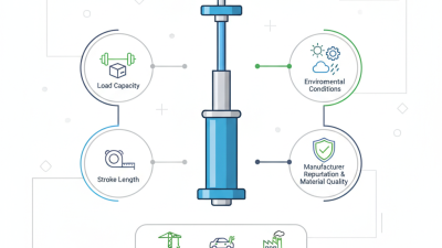
A cylinder’s basic force follows a simple formula: pressure multiplied by piston area. Yet real performance involves more than mathematics. Seal wear, side loading, contaminated oil, temperature, and incorrect mounting can reduce service life. Shur Lift Cylinders must therefore match the machine’s pressure, stroke, load, and operating environment. ISO 4413 also stresses safe hydraulic-system design, installation, and maintenance.
Hydraulic educator Brendan Casey offers a useful reminder: “Hydraulics is not a black art. It is a science.” That principle guides this article. We will examine cylinder construction, fluid movement, force generation, mounting, maintenance, and common failure signs. The explanation will remain practical, but not overly confident. Some applications need manufacturer confirmation. A cylinder that looks suitable may still fail under shock loads, uneven alignment, or repeated cycling. Understanding those limits helps operators choose Shur Lift Cylinders more safely and reliably.
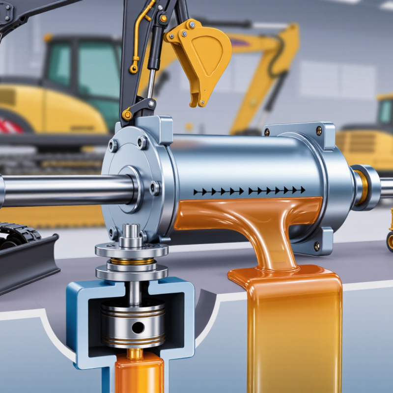
Ashur lift cylinder is a hydraulic actuator designed to raise, lower, tilt, or support equipment. It converts pressurized fluid into controlled linear movement. The main parts include a steel barrel, piston, piston rod, seals, ports, and mounting points. When hydraulic fluid enters one side of the barrel, it pushes the piston. The rod then extends or retracts, depending on fluid direction.
These cylinders appear on lifting platforms, trailers, agricultural equipment, and material-handling systems. Their lifting force depends on fluid pressure and piston area. A larger piston can produce greater force, but it may move more slowly. The cylinder length also determines the available stroke, or travel distance. Small design details matter.
In practical maintenance, clean fluid is essential. Dirt can damage seals and scratch the piston rod. A bent rod may cause uneven movement or leaks. Technicians usually inspect fittings, mounting pins, hoses, and seal areas before blaming the cylinder itself. That simple check prevents wrong repairs. Still, visual inspection has limits. Internal wear can remain hidden until the cylinder loses pressure or drifts under load. Smooth movement does not always mean perfect condition. Regular load checks and manufacturer-specified pressure limits help reduce unexpected failure.
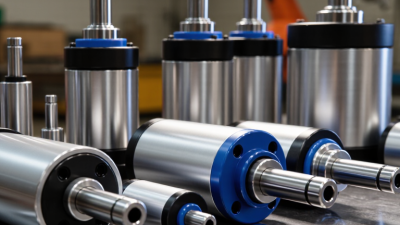
Shur lift cylinders convert hydraulic pressure into controlled linear movement. Their main parts include a steel barrel, piston, piston rod, seals, gland, ports, and mounting eyes. The barrel contains pressurized fluid. The piston separates the internal chambers, while the rod transfers force to the lifting mechanism.
Seals are small but critical. They limit fluid leakage around the rod and piston. A wiper seal also helps keep dust away from the internal chamber. Hydraulic ports direct fluid into one side or both sides of the piston. Some designs provide lifting power in one direction and rely on gravity for return movement. Others use pressure for both extension and retraction.
Structural design affects stability, service life, and lifting accuracy. A larger bore can produce greater force at the same pressure, but it may increase weight. A thicker rod resists bending, especially when loads are uneven. Mounting eyes must align with the machine frame. Poor alignment creates side loads, which can damage seals and deform the rod.
Small details matter. A polished rod surface reduces seal wear. Properly placed bushings support the rod near the gland. Relief protection can help manage unexpected pressure spikes. Yet no cylinder is perfect. Even a well-built unit may develop wear under dirt, overload, or repeated shock. Technicians should inspect leaks, rod scratches, loose mounts, and unusual movement before failure becomes obvious. Some problems hide quietly.
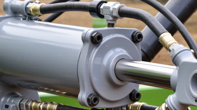
A lift cylinder converts hydraulic pressure into controlled linear movement. Its main parts include a steel barrel, sealed piston, polished rod, ports, and mounting pins. During operation, a pump draws hydraulic fluid from the reservoir. The control valve then directs pressurized fluid toward one side of the piston.
Pressure builds behind the piston. The piston moves forward, pushing the rod outward and raising the attached equipment. A seal around the rod limits fluid loss and helps block dust. The mounting points keep the cylinder aligned while the load shifts. Alignment matters more than many operators expect. Side force can damage seals, bend the rod, or create uneven wear.
When the valve changes position, fluid enters the opposite chamber. The piston then retracts, while displaced fluid returns through the return line and filter. The operator controls speed by adjusting flow, not pressure alone. A slow, steady movement is usually safer and easier to inspect. In field servicing, I would check leaks, unusual noise, and rod scoring before blaming the pump. That judgment is not perfect, especially when a blocked filter produces similar symptoms. Temperature also changes fluid behavior, so cold starts may feel sluggish. Clean fluid, correct seals, and regular pin inspection support reliable lifting performance.
What Are Shur Lift Cylinders and How Do They Work?
Shur lift cylinders are hydraulic actuators that convert fluid pressure into straight-line lifting force. A pump sends pressurized oil into one side of the cylinder. The oil pushes a piston, extending or retracting the attached rod. Seals control leakage, while the barrel guides the piston during movement. Simple in design, these cylinders can produce substantial force in compact spaces.
Common applications include dump bodies, trailer gates, agricultural tools, service platforms, and material-handling equipment. On a dump body, the cylinder raises a loaded bed smoothly, even when gravel shifts suddenly. In a tailgate system, controlled extension helps prevent harsh drops and unnecessary frame stress. Their performance depends on more than pressure alone. Bore diameter, rod size, stroke length, mounting angles, and load distribution all affect lifting capacity.
A correctly matched cylinder improves cycle speed and operator control. It can also reduce manual handling and limit mechanical wear. However, higher pressure is not always better. Excess pressure may damage seals, hoses, or mounting points. Field inspections should check rod scoring, oil seepage, loose pins, and uneven movement. Small leaks matter. They often become larger failures. In my experience, poor alignment causes problems that appear to be hydraulic faults. Engineers should verify the full load path before selecting a replacement. Real performance may fall below catalog figures when temperatures drop or loads are off-center.
| Data Dimension | Description | Practical Performance Relevance |
|---|---|---|
| Product Category | Shur Lift cylinders are hydraulic lift cylinders designed to produce controlled linear motion for raising, lowering, tilting, or positioning equipment and loads. | They provide high lifting force in a compact package and can be integrated into many mobile and stationary hydraulic systems. |
| Basic Operating Principle | A hydraulic pump sends pressurized fluid through a control valve into one side of the cylinder. Fluid pressure acts on the piston area and moves the piston rod in a straight line. | The cylinder converts hydraulic energy into mechanical force and linear movement. |
| Main Components | Typical components include a cylinder barrel, piston, piston rod, rod seal, piston seal, wiper seal, gland, end caps, ports, and mounting points. | Correct interaction between these parts helps maintain pressure, reduce leakage, guide the rod, and protect the internal surfaces from contamination. |
| Force Generation | Theoretical extension force is calculated as hydraulic pressure multiplied by the piston area: F = P × A. Retraction force is lower because the piston-rod area reduces the effective pressure area. | A larger bore or higher operating pressure generally increases force, while system limits, mounting loads, and safety factors must also be considered. |
| Motion Control | Cylinder speed depends mainly on fluid flow rate and effective piston area. Direction is controlled by a hydraulic directional valve. | Flow-control valves, counterbalance valves, and load-holding valves can help manage descent speed and prevent uncontrolled movement. |
| Common Cylinder Configuration | Double-acting cylinders use hydraulic pressure for both extension and retraction. Single-acting designs use hydraulic pressure in one direction and an external load, spring, or gravity for the return stroke. | Double-acting designs offer more positive control, while single-acting designs can be simpler for applications requiring powered lifting and gravity-assisted lowering. |
| Material-Handling Applications | Used in lift tables, loading platforms, warehouse equipment, dock systems, and other machinery that raises or positions materials. | Hydraulic actuation supports heavy loads while allowing controlled positioning and repeatable movement. |
| Agricultural Applications | Commonly applied to implement lifting, steering, adjustment, folding, and positioning functions on agricultural machinery. | The cylinders provide high force from the tractor or machine hydraulic system without requiring a separate electric actuator at every movement point. |
| Trailer and Utility Equipment | Applications may include dump bodies, tailgates, ramps, adjustable platforms, and other utility equipment requiring powered lifting or tipping. | The design can deliver substantial force while keeping the actuator length and installation footprint relatively compact. |
| Construction and Industrial Equipment | Hydraulic lift cylinders are used for access platforms, machine adjustments, compact lifting systems, and industrial fixtures. | They are suitable for demanding duty cycles when correctly sized for load, stroke, speed, alignment, and environmental conditions. |
| Key Performance Benefits | High force density, direct linear motion, controllable speed, reversible movement in double-acting systems, and compatibility with centralized hydraulic power. | These characteristics can improve lifting capability, positioning control, layout flexibility, and equipment productivity. |
| Durability Factors | Service life depends on hydraulic-fluid cleanliness, seal compatibility, rod surface condition, side loading, corrosion exposure, temperature, and correct installation. | Proper filtration, lubrication where specified, rod protection, and regular inspection help reduce premature seal and component wear. |
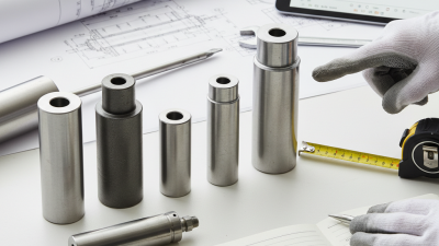
| Sizing Considerations | Selection should account for required force, stroke length, retracted and extended dimensions, operating pressure, flow rate, mounting style, rod diameter, buckling risk, and duty cycle. | Correct sizing improves stability and efficiency and helps prevent overload, excessive deflection, slow operation, or rod damage. |
| Safety Requirements | Loads should be mechanically supported during maintenance, and the hydraulic system should be depressurized before service. Hoses, fittings, mounts, and load-holding devices must be inspected regularly. | Hydraulic pressure can store significant energy; safe isolation and load restraint are essential for protecting operators and equipment. |
Lift cylinders convert hydraulic pressure into controlled vertical movement. In service equipment, they may raise platforms, beds, or support arms. A pump sends fluid into the cylinder, pushing a piston and extending the rod. Reversing fluid flow retracts it. Movement should remain smooth, without sudden drops, scraping sounds, or visible rod damage.
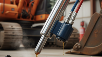
Maintenance begins with a clean inspection area. Check hoses for bulges, wet fittings, and cracked outer layers. Examine the polished rod for rust, scoring, or dried fluid. Small leaks can become serious under pressure. Follow the equipment manufacturer’s service intervals, use the specified hydraulic fluid, and keep dirt away from open connections. Never work beneath a raised load without approved mechanical supports. Hydraulic pressure may remain trapped after the control is released. That detail is easy to overlook.
Tips: Lower the equipment fully before inspection. Wipe the rod before checking for fresh oil. If the cylinder drifts, inspect for internal seal wear, a leaking valve, or trapped air. Slow lifting can indicate low fluid, a restricted filter, or a weak pump. Do not tighten fittings while the system is pressurized. Stop using the equipment when cracks, severe leaks, or uncontrolled movement appear. A visual check is helpful, but it is not proof of safety. Test movement from a safe position, and record unusual sounds or repeated repairs for qualified service personnel.