+86-13349293098


Selecting the right Hydro Cylinder starts with the job it must perform, not just the machine it fits. The cylinder must provide enough force and travel while fitting the available space. Define the load, required stroke, operating pressure, and duty cycle. Note whether the load moves smoothly or starts under resistance; that difference can affect sizing. Measure mounting points, retracted length, and extension clearance before comparing models. A small mismatch matters.
Check the manufacturer’s specifications for rated pressure, bore, rod diameter, seals, and compatible fluid. Confirm force for both extension and retraction, since the rod reduces effective area on the pull stroke. Do not guess. Maximum pressure is not automatically a suitable continuous operating pressure. Account for pressure losses, temperature, and how often the cylinder cycles. Dust, moisture, and corrosive surroundings may call for different materials or protection. Side loading can shorten service life, so review alignment and mounting carefully. Keep it serviceable.
Compare candidate cylinders against the machine’s real operating conditions, not only a catalog headline. Check that hoses, valves, and the power unit can support the selected cylinder’s requirements. For unusual loads or uncertain measurements, ask the manufacturer or a qualified hydraulic specialist to review the figures. A datasheet helps, but it cannot reveal every installation problem. Measure again if the space is tight. It is easy to overlook one bracket or connection, and that deserves a second look before ordering.
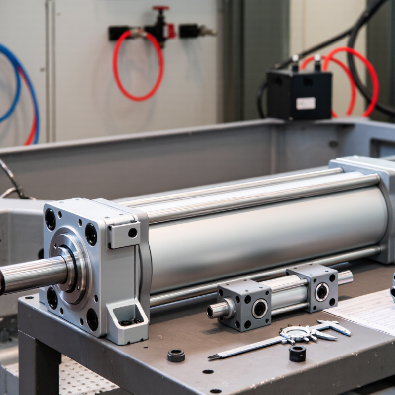
Define Load, Stroke, and Duty Cycle Before Selecting a Hydraulic Cylinder
Start by defining the load the cylinder must move or hold. Include the weight, friction, acceleration, and any force needed to overcome resistance. A steel gate may feel light when balanced, yet bind under uneven loading. Check the system’s working pressure and mounting geometry too. Side loads can damage a rod even when the rated force seems sufficient. A simple load estimate is useful, but it may miss real operating conditions.
Stroke is the distance the rod must travel between its retracted and extended positions. Measure the machine’s actual movement, including clearance at both ends. Too little stroke may leave a clamp loose; too much can create interference or waste space. Duty cycle matters just as much. Record how often the cylinder moves, how long it stays under pressure, and how quickly it cycles. Frequent operation can build heat and accelerate seal wear.
Tips: Measure it twice. Note the load, stroke, pressure, cycle frequency, and operating temperature before comparing cylinder options. Check alignment and available space with the machine in its working position. If the load shifts or the cycle is unusually demanding, ask a qualified hydraulic engineer to review the sizing. Real equipment is rarely as tidy as a drawing suggests.
Start with the force your machine must deliver and the pressure available at the cylinder. Rearrange the formula to find the required piston area: Area (cm²) = Force (kN) × 10 ÷ Pressure (MPa). For example, a 40 kN push at 16 MPa needs 25 cm² of piston area. For a round bore, diameter in centimeters equals the square root of area × 4 ÷ π. That gives roughly 5.64 cm, or 56 mm. Numbers help, but the estimate is only a starting point.
Check which side of the piston supplies force. On the rod side, the rod reduces the working area, so the cylinder produces less force at the same pressure. Also allow for friction, pressure losses, and changing loads. Use the pressure measured or expected at the cylinder, not just the pump’s rated pressure. I have seen a tidy calculation look convincing, then fall short under real operating conditions. That is worth checking before selecting a bore.
Tips: Convert units before calculating, and confirm whether the required force is pushing or pulling. Add an appropriate engineering margin for your duty cycle, then verify the result against cylinder specifications and operating limits. A slightly larger bore is not automatically better; it can change speed, oil demand, and system performance.
ISO 6020-2 and ISO 6022 point to two different pressure classes. ISO 6020-2:2015 covers cylinders rated at 16 MPa, or 160 bar; ISO 6022:2006 specifies the 25 MPa, or 250 bar, series. These figures are nominal working-pressure ratings, not permission to ignore pressure spikes. Check the cylinder documentation and the machine’s measured operating pressure before choosing.
For a press running steadily near 140 bar, a 160-bar cylinder may appear suitable, but little margin remains for shock loads or pressure surges. A 250-bar ISO 6022 cylinder can offer more headroom, though it may be larger or heavier than the installation allows. Measure the available mounting space, pin dimensions, stroke, and rod alignment. A pressure upgrade alone will not fix side loading.
Also check the full hydraulic circuit: hoses, valves, seals, and fittings must tolerate the system’s maximum pressure. ISO ratings provide a useful comparison, but actual service conditions matter. A gauge reading during one cycle may miss a brief spike. That detail is easy to overlook. The standards cited here—ISO 6020-2:2015 and ISO 6022:2006—give the pressure-class figures; confirm the required safety margin with a qualified hydraulic engineer.
A hydraulic cylinder should be checked across its full stroke, not only at the position where it looks strongest. During extension, the exposed rod becomes longer and more vulnerable to buckling under compression. Compare the maximum pushing force with the rod’s unsupported length, cylinder bore, and end conditions. A rod that works safely when retracted may bend when fully extended. Small details matter.
Mounting geometry changes the loads the cylinder actually sees. A clevis or trunnion mount can allow useful pivoting, but the pivots must move freely and remain aligned. Fixed mounts need particularly careful alignment. If the load path shifts as a machine moves, the rod may be pushed sideways instead of straight. Even a modest offset can wear seals, score the rod, and shorten service life. Not always obvious.
Trace the force and direction at several points through the stroke, including startup, reversal, and the final few inches. Check whether the load stays centered, whether pins bind, and whether guides support moving parts independently of the cylinder. A simple sketch with stroke positions and load arrows often exposes problems early. It is easy to overtrust a neat calculation; real frames flex, and mounts are not always perfectly square. Use calculations as a screening tool, then verify clearances and alignment on the actual assembly.
Choosing seals, cushioning, and oil cleanliness together helps a hydro cylinder work reliably in its actual operating conditions. Seal material should match the hydraulic fluid, temperature range, pressure, and rod speed. A seal that performs well in cool indoor service may wear faster under heat or frequent cycling. Check fluid compatibility with the cylinder supplier, and consider dust or moisture around the rod. Small details matter.
Cushioning controls the piston near the end of its stroke. For a heavy load moving quickly, suitable cushioning can reduce impact and noise; excessive cushioning may slow the cycle. Ask whether cushioning is fixed or adjustable, and test it at the expected load and speed. Oil cleanliness matters, too. ISO 4406 codes report particle levels in three size ranges; lower code numbers indicate cleaner oil. For example, a reading such as 18/16/13 is a cleanliness code, not a complete maintenance plan. Set the target with the cylinder and system requirements in mind, then check filtration and sample oil near the machine. The right target can be easy to assume—and easy to get wrong. Recheck it after commissioning, since new hoses or repairs may introduce contamination.
Specify seals, cushioning, and oil cleanliness using ISO 4406 codes.
ISO 4406 codes classify the number of particles in one millilitre of fluid at ≥4, ≥6, and ≥14 μm(c). The bars show the upper concentration boundary for each code range; the logarithmic scale makes the different particle-size counts easier to compare. Use the cleanliness target specified for your system, and select cylinder seals and cushioning for its fluid, pressure, temperature, speed, and load conditions.